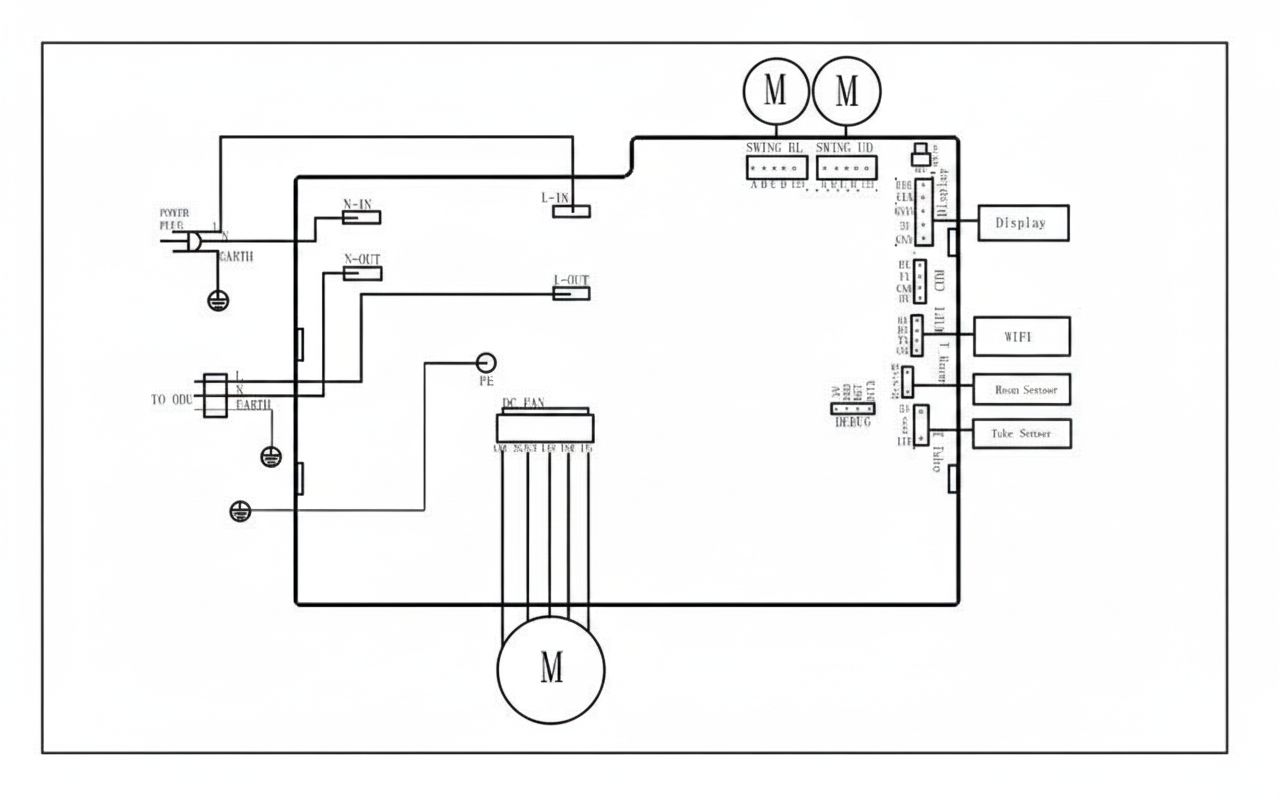
Wiring Diagram
Make sure that the color of wires of the outdoor unit and the terminal No. are the same as those of the indoor unit.
Models:
For above models, the power supply are connected from indoor unit.
Fixed Speed PCB Wiring Diagram
| E1 | Indoor ambient temperature sensor fault |
| E2 | Indore Coil temperature sensor fault |
| E5 | Indoor fan fault |
| SL | Means comes for 5sec at the beginning of function |
| CL | Self-clean feature is enable. |
| dF | To indicate Defrost error |